Build your own keyboard
Out of all the peripherals out there, I like keyboards the most.
Assemble your own keyboard
Out of all the peripherals out there, I like keyboards the most.
I like split keyboards and I like building keyboards. This is a guide on how you too, can build a keyboard. Specifically I'm going to walk you through how to build a redox, split keyboard.
You will need to know how to solder and have the necessary equipment.
Check out https://falba.tech and https://github.com/mattdibi/redox-keyboard
class="graf graf--figure graf--layoutOutsetCenter graf-after--p graf--trailing"> 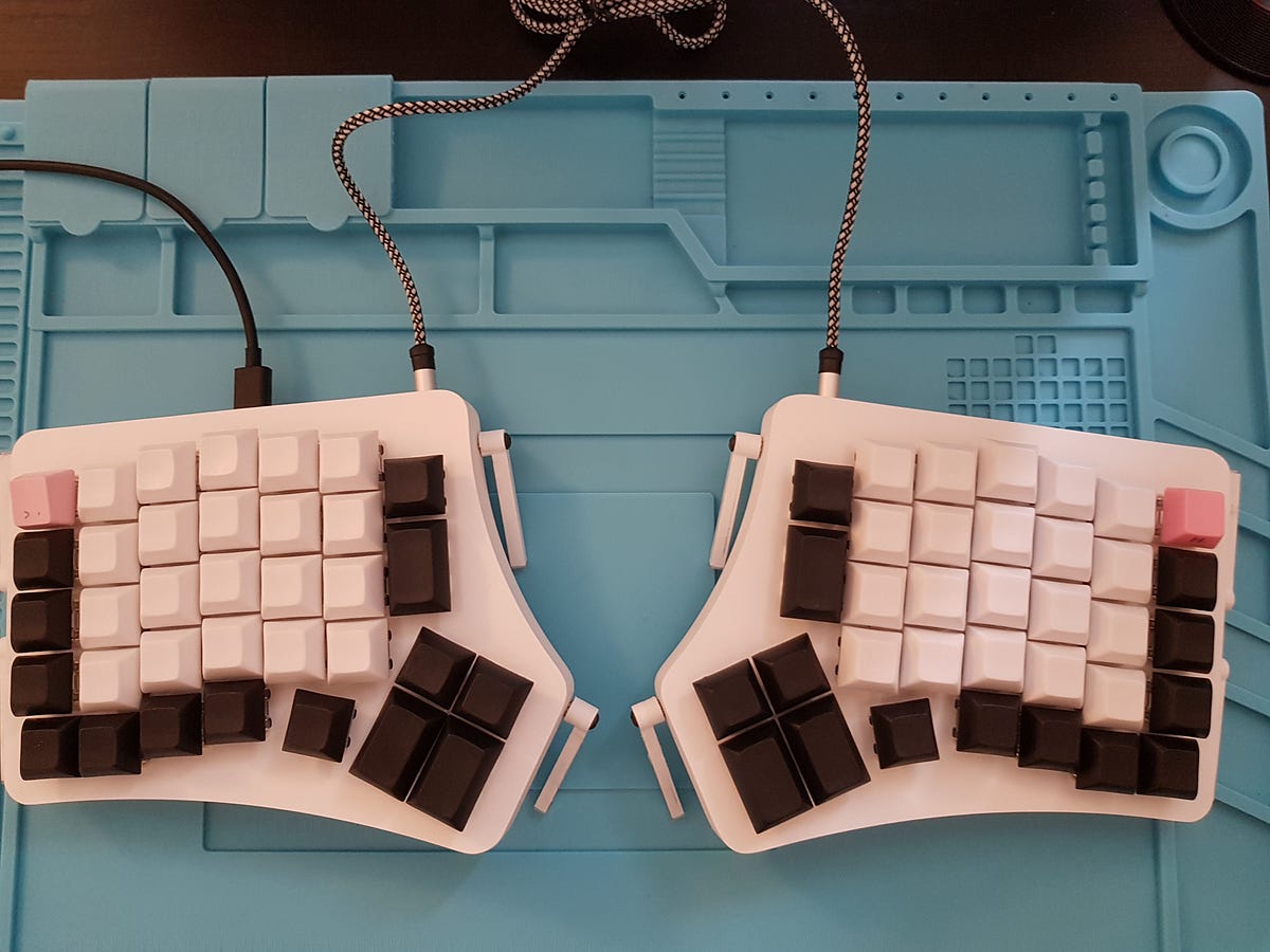
Get all the components out! With your index finder bend the diodes in a Π position. Then remove them from the paper holding them together.
The two PCB boards are identical. All the components will be soldered on one side, except from the switches. Pick a PCB and start putting the diodes through the holes. The diodes go in in the circle and square holes. Orientation in diodes matters. Black end = square. This is important!
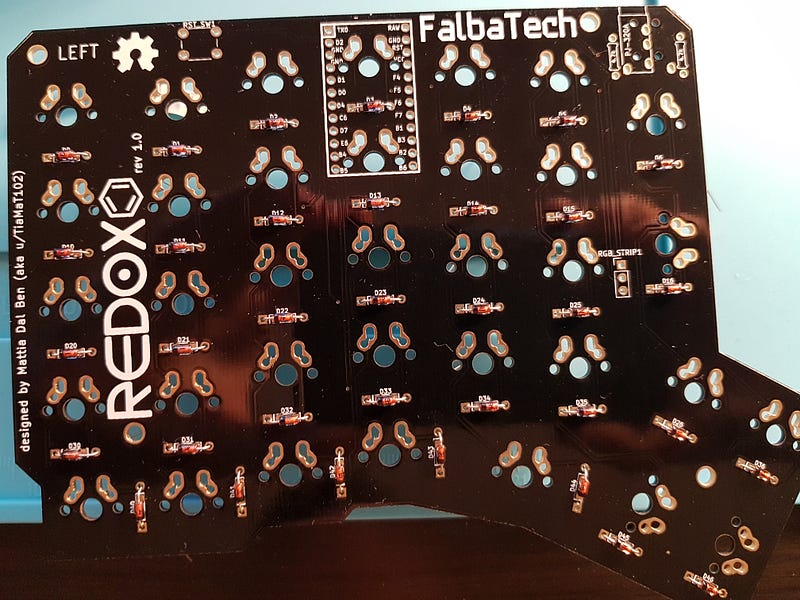
As you put the diodes through the holes, you want to open the diode legs enough so that they can hold on their own. The reason why although the PCB clearly has LEFT written , the switches are going to be soldered on the other side.
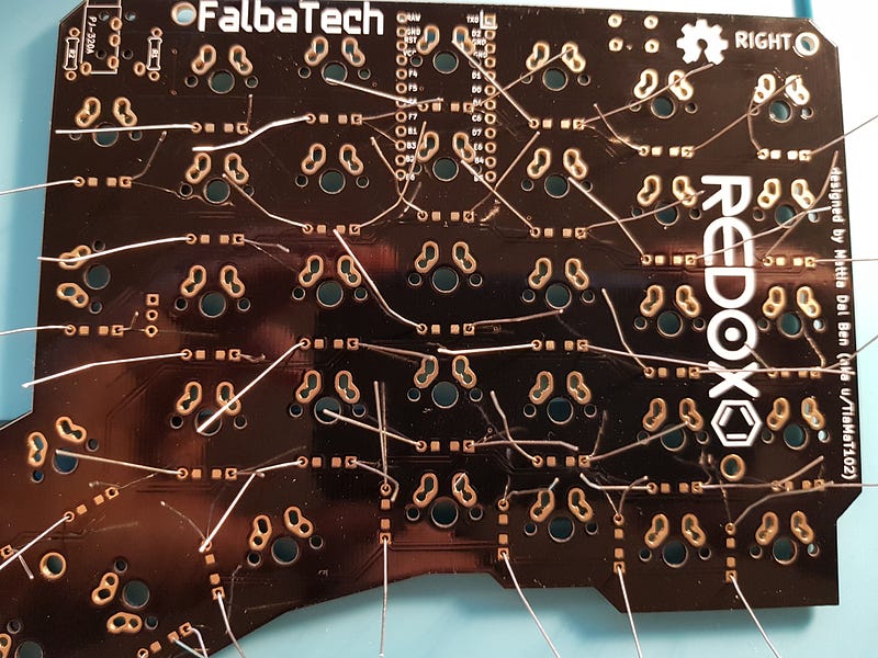
The other PCB should look like this
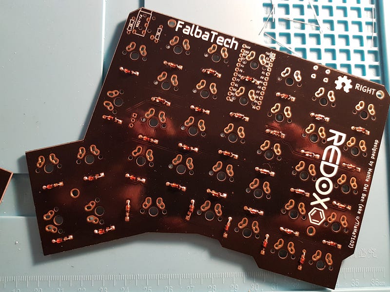
Now it's time for the TRRS jack and the reset button. The reset button will help you reset your keyboard's keymap. I used capton tape to hold them in place. Place the components in the areas marked by the PCB. The reset button cannot be inserted any other way. Orientation of resistors doesn't matter
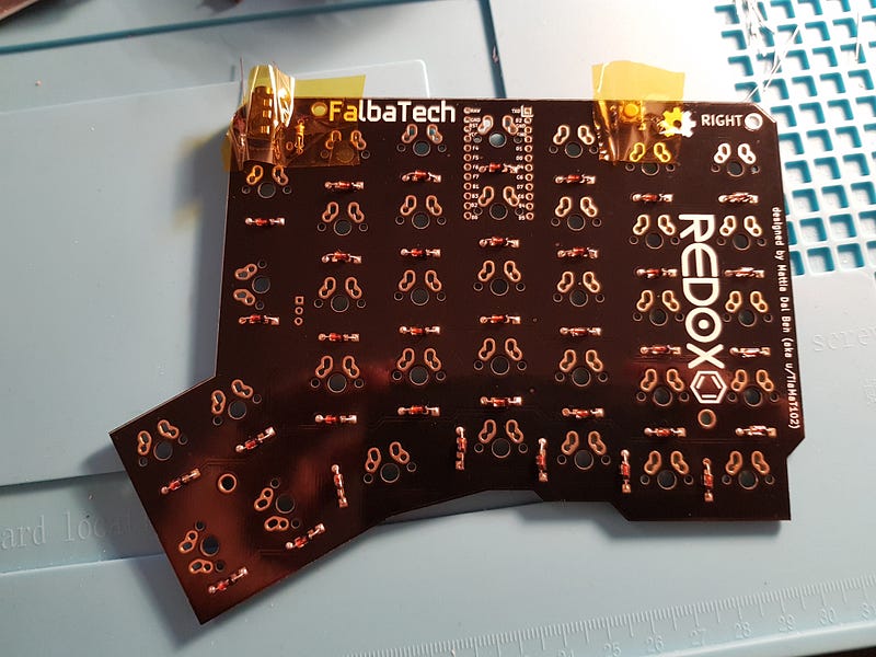
Then do the same trick for the pins that will hold together the arduino
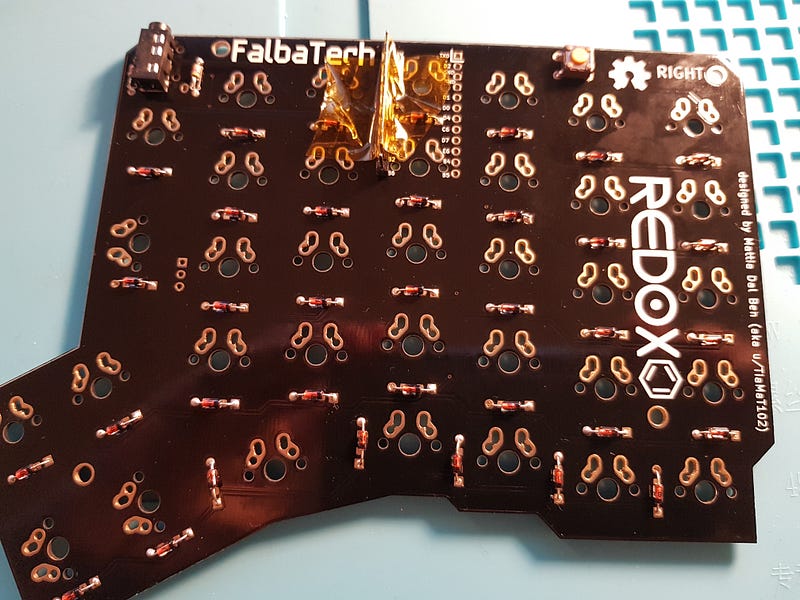
From another angle
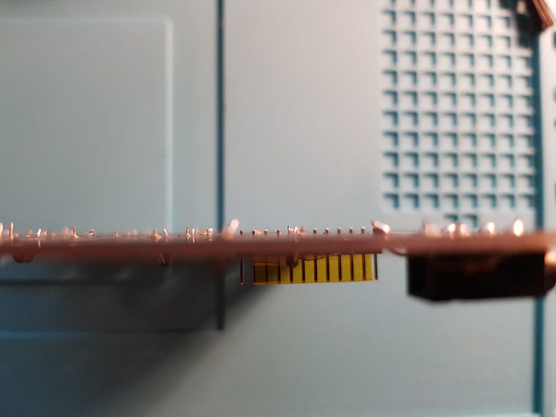
Do this on both PCB. If for any reason they are not straight or at the wrong angle, try to insert the arduino in place. Now is the time to do it. Feel free to try and desolder or slightly adjust the pins so that the arduino can fit. However do not solder the arduino just yet.
It's first time to make sure that it's working and to flash with QMK!
If you're running linux it might be as simple as
git clone https://github.com/qmk/qmk_firmware
cd qmk_firmware
sudo make redox:default:avrdude
Plug your arduino to your computer , and then short GND and RST like so.
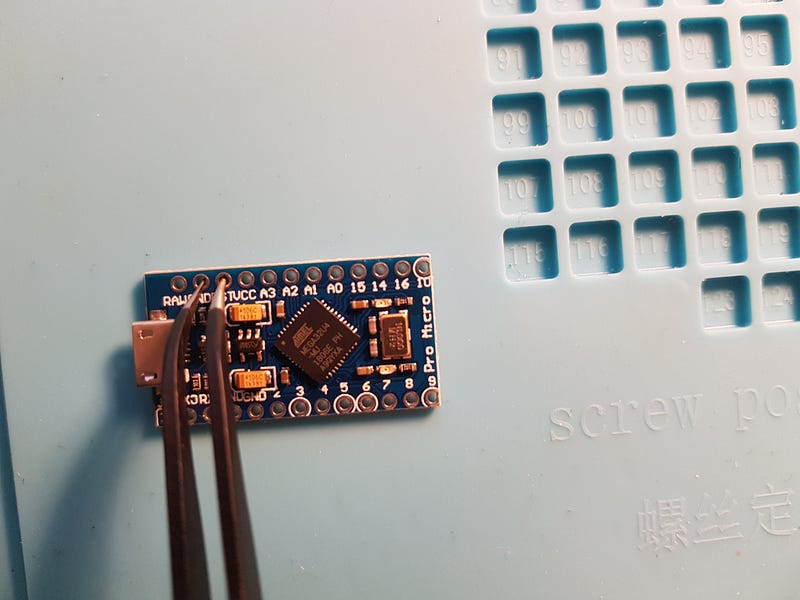
If you are successful you should see something like.
avrdude: verifying ...
avrdude: 24128 bytes of flash verified
avrdude: safemode: Fuses OK (E:FB, H:D8, L:FF)
avrdude done. Thank you.
Repeat the same on the other arduino as well.
Good you have working , flashed arduinos.
Now before you solder the arduino, you need to solder some switches in place. Otherwise you won't be able to in the future.
But before we start soldering the switches , check if the case is right. Some 3D printed cases might have minor imperfections
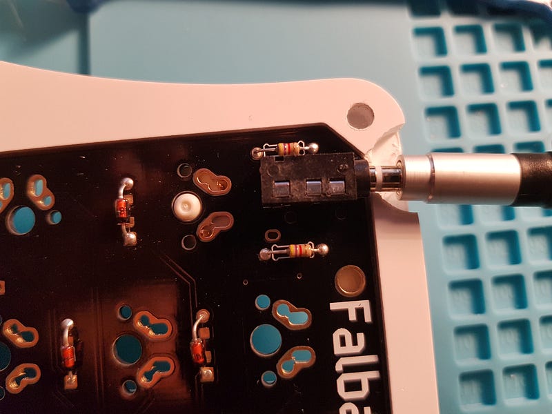
Now once you make sure that the TRRS jack is accessible it's time to mount the switches on the case and solder them
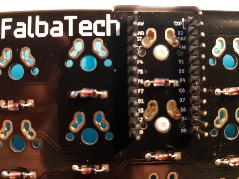
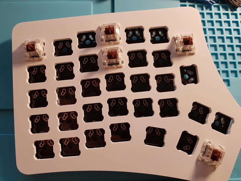
Make sure to mount and solder these switches! I prefer to solder a couple of switches around the board as well.
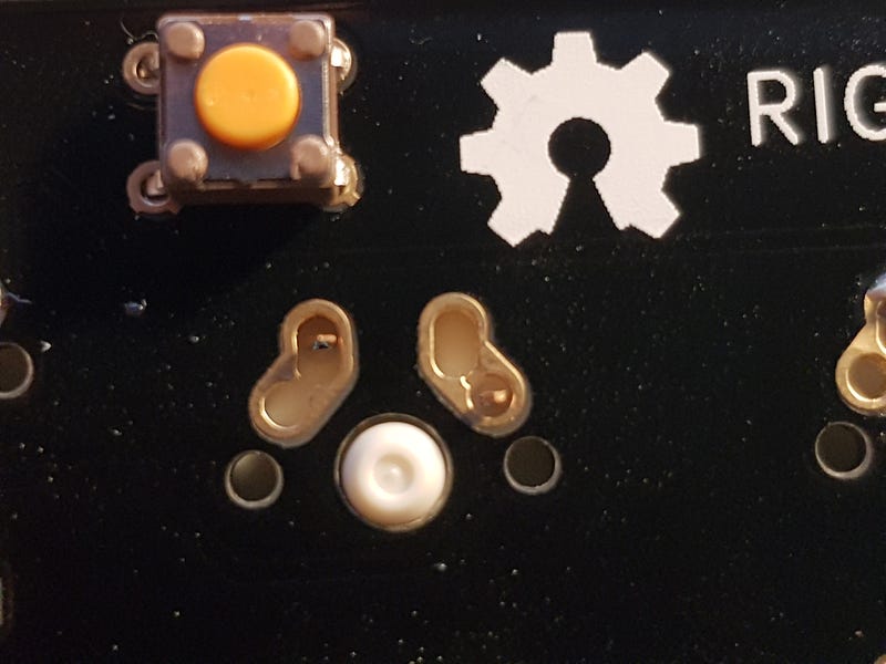
Now orientation of the arduino matters as well. Make sure that the labels in the arduino match the labels in the PCB (duh!) .
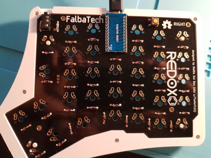
On the other PCB, the arduino will go the other way (The LEDs and the die will be facing you)
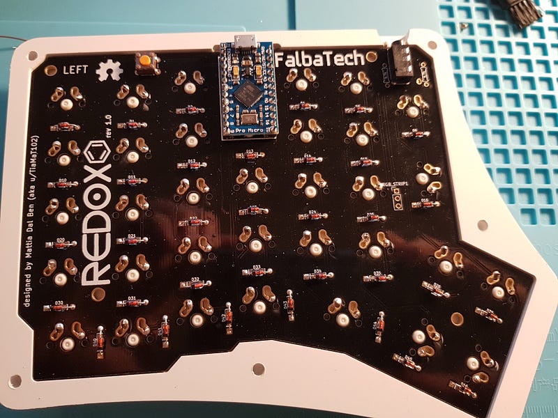
The switches should look like this on the other end.
The moment of truth has arrived. Plug your usb cable to your keyboard and start typing with those keys that you've soldered. Congratulations!
Keep mounting, and soldering these switches. Finally don't forget the keycaps.
There are a lot of kit keyboards out there. Admittedly I do like the split kind because, anecdotally , they are more ergonomic and make me hunch less.
Split Keyboard Parts
*Parts for building split keyboards like the Nyquist, Viterbi, Levinson, and Iris.*keeb.io{.js-mixtapeImage .mixtapeImage .u-ignoreBlock media-id="478050e1c67c59cf9dec14e6fcfaae8e" thumbnail-img-id="0js7SRoQKd36Fdo5c" style="background-image: url(https://cdn-images-1.medium.com/fit/c/160/160/0js7SRoQKd36Fdo5c);"}
Kits Archives | MechBoardsUK
Edit descriptionmechboards.co.uk{.js-mixtapeImage .mixtapeImage .u-ignoreBlock media-id="e2edc76f9aed0c7f4566bc244041aae9" thumbnail-img-id="0xJ2KH6TQSQQGXcLO" style="background-image: url(https://cdn-images-1.medium.com/fit/c/160/160/0xJ2KH6TQSQQGXcLO);"}
and of course a whole subreddit dedicated to it. https://www.reddit.com/r/MechanicalKeyboard
Happy typing.